Connecting the Ncompass™ 4000
 Ensure all items are powered down before connecting the Ncompass™ Analyzer and/or the CC.
Connect as follows:
Ø Locate the 37-pin male D-sub connector cable. Connect one end of the cable to the female ISA Adaptor port located on the left side panel of the computer body.
Ø Connect the other end of the 37-pin D-sub connector to either of the 2 female D-sub connections marked ‘COMPUTER’ located on the top panel of the portable Analyzer or at the rear panel of the rack mounted version.
Ø Making sure that the Analyzer is switched 'OFF', connect the IEC power supply cable (supplied) to the Analyzer ‘POWER’ socket.
Ø Connect the IEC power supply cable (supplied) to the computer power socket located on the left side panel of the computer body.
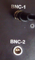
Ø Using the BNC to male Banana Jack cable (supplied), connect the BNC end to either of the BNC terminals marked ‘BNC-1’ and ‘BNC-2’ (identified as INSTR-1 and INSTR-2 on later models) on the Analyzer.
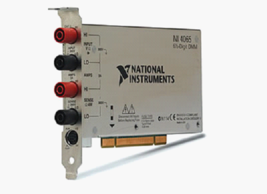
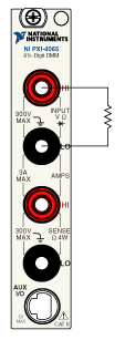
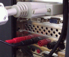
Ø If the CC is supplied with an internal DMM, standard is a NI-4065PCI DMM, then connect the RED and BLACK Banana Jacks to the rear-most jack sockets located on the left side panel of the computer body, marked CATII Hi for red fly-lead and CATII Lo for the black fly-lead (shown by the 'resistor' symbol in the diagram below); other peripheral equipment and connection methods can be found under the Using Peripheral Test Equipment topic.