IFD-Beta method is ideal for testing UUTs with larger test point count than is available on the IFD™ TE. Or it could be used, for example, for testing a long cable loom front to back though an aircraft or installation where a common return may be employed to reduce test point count, and cable run lengths. In this case, it may be that it is preferred not to run separate test lines to both sides of the aircraft loom, but instead connect all the wires at one end of the cable loom to discrete test points on the IFD™ TE, and then on the other end of the loom, ‘gang’ a common with a simple modified connector or similar (shorting link); this common return would then be connected to a switchable test point on the IFD™ TE; as shown in the diagram below, for example, TP16.
IFD-Beta method uses the common ground returns designed into the ITA and then connected to the IFD™ TE. While this method, provides a simpler form of ITA for UUT testing, this method limits the range of test functions available to the User because it is only optimised for IFD testing.
Other scenarios where this mode is useful:
Ø There are not enough test points on the IFD™ TE to provide full coverage of the UUT in one test.
Ø A quick Intermittence test needs to be carried out and there is, perhaps, no real requirement to carry out further types of discrete testing.
Ø Reduce the complexity of the ITA.
Disadvantages of using this mode:
Ø While optimised for quick Intermittence Testing, the ability to diagnosis and thus isolate the intermittent event is limited.
Ø Other test functions and the flexibility of switching specific test points to supported instrumentation is extremely limited.
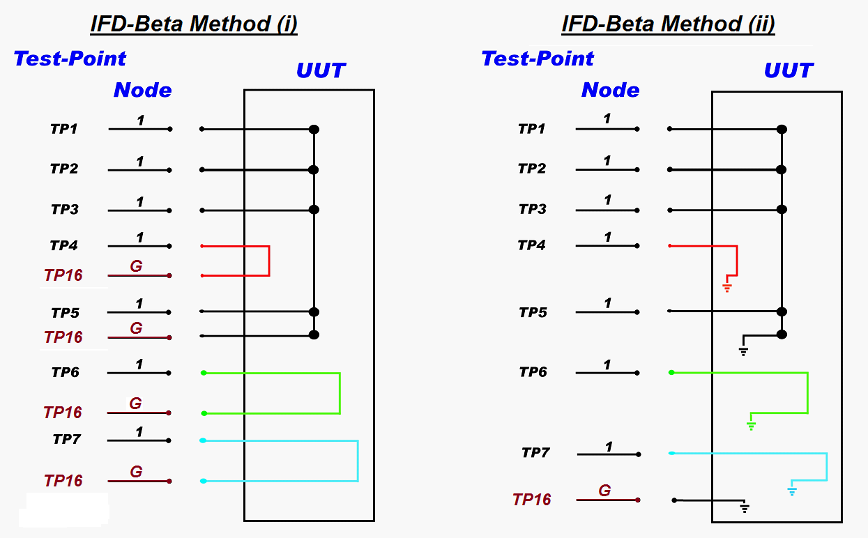
The diagrams below illustrates two examples of this method of connectivity in IFD-Beta Method:
Ø IFD-Beta Method (i) illustrates an example where all the ‘test ground’ lines are connected together at TP16
Ø IFD-Beta Method (i) illustrates a single ganged 'test ground' line going to TP16 and the internals of the UUT used as return path.
Ø Nodes for both the examples shown are limited to 1; this is because all of the test points are common to the same nodal ground.
Ø For legacy equipment Model0 & Model1 & Model5, pins 17/50 of the J-connectors have hard-wired 'test ground' and so a dedicated test point (TP16 used in this example above) is not needed, instead all the points shown above on TP16 can be connected to either pins 17/50. However, note that by building ITA that use pins 17/50 for legacy equipment, this will mean the ITA will have to be adapted for newer equipment; therefore, it is recommended that pins 17/50 are not used in new ITA designs.