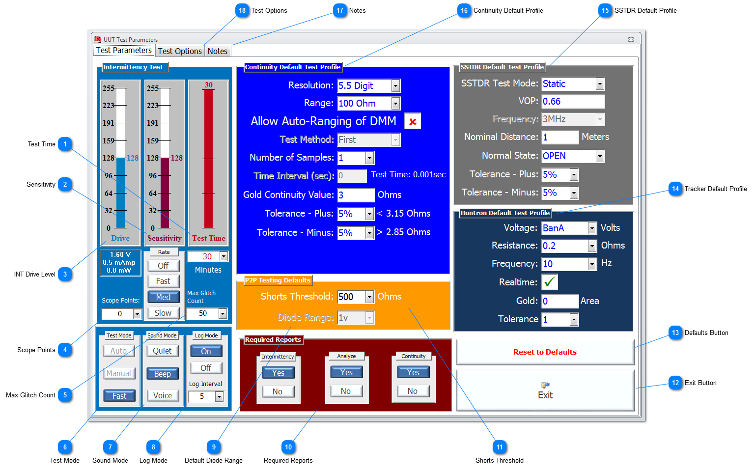
Once the test parameters have been set, they will remain constant during any test called up by Ncompass™ software menu system or NODES™ until they are manually changed using this form or they are changed by the User with the designated function keys during testing.
As a general rule the values for Drive Level and Sensitivity should be set to a point where the test picks up definite events in connectivity but not ambient noise. This may require the User to experiment to find these levels to ensure the system operates at or below this threshold; this may vary from item to item, and the environment in which testing is being carried out. In the majority of UUTs the events caused by intermittency will be obvious.
 Test Time Set the test duration in minutes for Intermittence testing. This time may need to reflect the time needed to stimulate the UUT or perform environmental stress cycles, such temperature or humidity cycling. The test can be paused at anytime during the test time set without loss of test data.
|
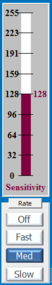
 Sensitivity Sets the level of sensitivity for the Intermittence Test. It ranges from 1 to 255 with 255 being the maximum sensitivity. If the sensitivity is set too high, the system may respond to variations that could be attributed to just ambient ‘noise’. Set the sensitivity low initially to capture more frequent intermittency, and then consider increasing the sensitivity gradually in steps to continue detecting faults while remaining low enough to prevent reaching the ambient ‘noise’ level. The Rate of change for increasing both Sensitivity and Drive values can also be set to Fast/Med/Slow; there is no Rate of change for decreasing these parameters. 'Med' is set as the default.
|
 INT Drive Level Set the drive level from a range of 1 to 255, with 255 equating to a maximum voltage of 3.2volts. The drive level is the amount of voltage applied to the UUT as the analogue stimuli; the maximum current is shown in milliamps and can only be a maximum of 1.1mA. The Rate of change for increasing this parameter is as described for Sensitivity.
|
 Scope Points Set the resolution of the Scope points plotted in the Scope area on the Legacy Intermittence Test screen. For Fast mode, the Scope Points are limited to a maximum of 150. |
 Max Glitch Count Sets the number of events (glitches) that are captured and displayed prior to automatically grounding the associated test point; this allows the IFD™ TE to spend valuable time processing and displaying new events from other TPs, rather than the CC being tied up processing intermittent faults that have been detected and isolated.
|
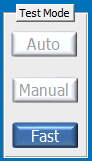
 Test Mode This parameter is only relevant to Legacy Intermittence, and has the following modes of operation:
-
Auto mode ramps the sensitivity up automatically until there is an event detected and then resets to the predetermined level.
-
Manual mode allows the User to change the Drive and Sensitivity settings during the test using the 'Function' keys.
-
Fast mode optimises the operation of the Intermittent function to provide capability for catching multiple faults; this option restricts the level of scope points to <100.
|
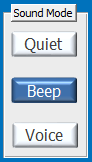
 Sound Mode The IFD™ TE has a number of sound modes available. This includes a built-in synthesized voice option, which will call out the nomenclature of those failing test points as they occur. Set to Voice for this option (USB sound output is required as an option for VIFD™ or a sound card required for CC for IDFIS™). Other options are Quiet and Beep.
|
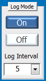
 Log Mode Set the Log mode to ON to record every intermittent event as an individual line entry onto a dedicated log file; this data can then be used for compilation into the UUT Results Report Summary. If set to OFF, all the intermittent events are simply summaries by test point. The Log interval is in seconds, and logs the data to an external file at the interval set. The default is set at 5secs.
|
 Default Diode Range Set the maximum voltage to be used in Diode Testing Profiles; it is recommended to use 1v as the default to ensure that sensitive components are not damaged inadvertently.
|
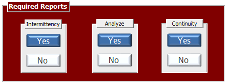
 Required Reports For legacy Intermittence and Point2Point applications pre Ver1.232
Set the reports required by each specific test. If set to YES, a report will be generated by the relevant test program and will be available for the User to compile into a summary report for the UUT, including the UUT SerNo, Operator and Date/Time of test; see Results for more details. All applications post Ver1.232, will always create csv files of all test data and capture to pdf, regardless of the settings set here. |
 Shorts Threshold Set the default Shorts Threshold levels in Ohms for the Shorts Testing. |
 Exit Button Click to Exit from Test Parameter and return to the calling form.
|
 Defaults Button Click to reset all the Test Parameters to the default settings.
|
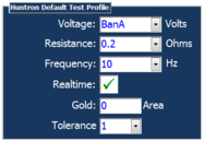
 Tracker Default Profile There is an option to fit a Huntron Tracker to certain models of IFD™ TE, especially VIFD™. When a Tracker is fitted, or the Tracker application is run in simulated mode, the User can create Test Profiles. These newly added Test Profiles will be initially created with the defaults set here. If these defaults are changed, then existing Test Profiles are not affected. |
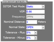
 SSTDR Default Profile There is an option to fit a Livewire SSTDR to certain models of IFD™ TE, especially VIFD™. When a SSTDR is fitted, or the SSTDR application is run in simulated mode, the User can create Test Profiles. These newly added Test Profiles will be initially created with the defaults set here. If these defaults are changed, then existing Test Profiles are not affected. |
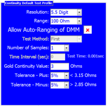
 Continuity Default Profile All models of IFD™ TE will be deployed with a DMM capability. When a UUT has TPs added, they will automatically be assigned a default Test Profile called CON-Default. This Test Profile, and any subsequent continuity Test Profiles added to a specific TP, will initially have their profile parameter set to the defaults that are set here. If these defaults are changed, then existing Test Profiles are not affected. |
 Notes Select this tab, and enter in the blue field, notes that may be particular for the UUT, and its associated testing parameters.
|
 Test Options Selecting the Test Options tab allows the User to change the settings and options for a range of different tests. This only affects legacy applications pre Ver1.232
|
Made with help of Dr.Explain
|