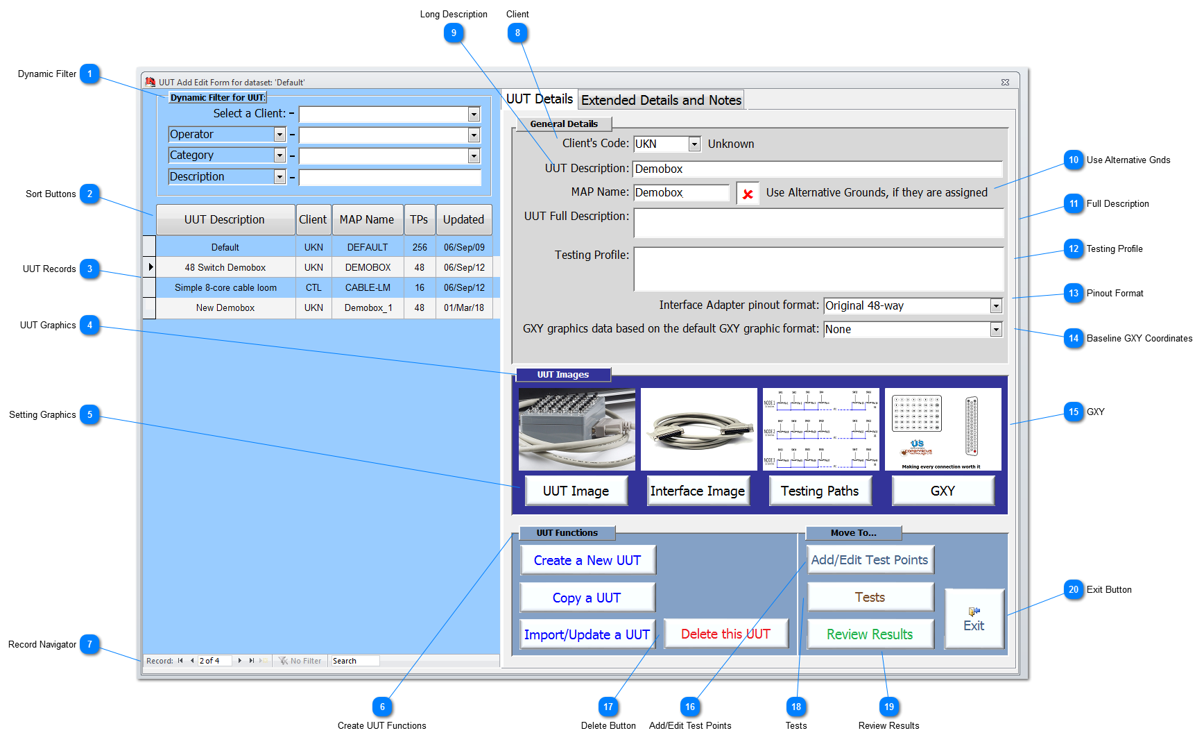
UUT Add/Edit
UUT Graphics 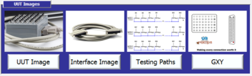 Each UUT has 4 graphics that can be assigned. All graphic files have to be valid graphic images as either .JPG, .PNG or .BMP file formats. Double-click on any of the graphics to enlarge them to full size if the screen permits; to save disc space, reduce loading time and maintain resolution, use /PNG where possible.
See UUT Graphics for more details on how graphics are used throughout the testing and reporting process.
|
Setting Graphics  Each graphic can be changed by clicking on its associated button. This will open a Windows dialog which will allow the User to navigate to the desired graphic. The User must ensure that the graphics are valid graphic images. The User can select a graphic from anywhere on the system and they will then be given the opportunity to copy the selected graphic to the correct folder with the Folder Structure.
|
Create UUT Functions  Use these buttons to create new UUT to be used within the current dataset. Follow the links for more information on Create a New UUT, Copy a UUT, Import/Update a UUT.
|
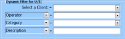
Client Using the dropdown select the Client that the UUT belongs to. The dropdown displays all the Clients held on the system (which can also be used for Operators too). If an entry is not in the list, double-click in the field to display the Client Lookup; you have to be assigned the necessary authorisation to carry out this task.
|
Use Alternative Gnds In some nodes there are multiple TPs and this can result in having a complex circuit. In some cases, it may be necessary to assign Alternative grounds to help with fault isolation, see more on different ground assignments Test Points Add/Edit. To automatically use this assigned Alternative Grounds, check this option (shown unchecked).
|
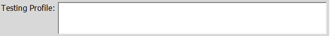
GXY  While the use of this specific graphic is covered under UUT Graphics, the GXY Graphic is the main graphic used throughout the creation of the UUT, the Add/Edit of TPs, all the testing applications and Click&Test™.
It is important that this graphic is a valid .PNG or .BMP file, which is why (because of its criticality) the file format is continually checked throughout to ensure that is has not been corrupted at any stage. If found to be corrupted, then the default GXY graphic will be loaded; if this happens then repair/replace/redraw the GXY graphic and overwrite the original file in the correct folder as detailed in Folder Structure. It is highly recommended that the bottom right hand corner (approx 400 wide and 25 high) is kept clear because a time-date stamp is place in this area when the GXY is made into a PDF for reporting results.
|
Add/Edit Test Points Click to Add/Edit Test Points for the current UUT.
|
Delete Button Click to Delete a UUT, a warning will appear for the User to confirm before the delete is executed. If the current dataset has results from tests performed using this UUT profile, then the User will not be allowed to delete the selected UUT.
A User has to hold the relevant authorisations to complete this function; see User Add/Edit for more details.
|
Tests Click to display the IFD™ Tests form. From this form, the User will be able to set the testing parameters and run IFD™ test functions for a UUT. In addition, there is also a facility to simulate the IFD™ hardware, to allow the User to simulate running test functions on a laptop/desktop computer for training or validating a UUT configuration is ready for test.
|
Review Results Click to review all the results data held for the connected dataset. The Results Review form allows users to navigate all the results for Intermittency, Continuity and Shorts, and filter the results by UUT, Serial No and other User defined parameters.
|