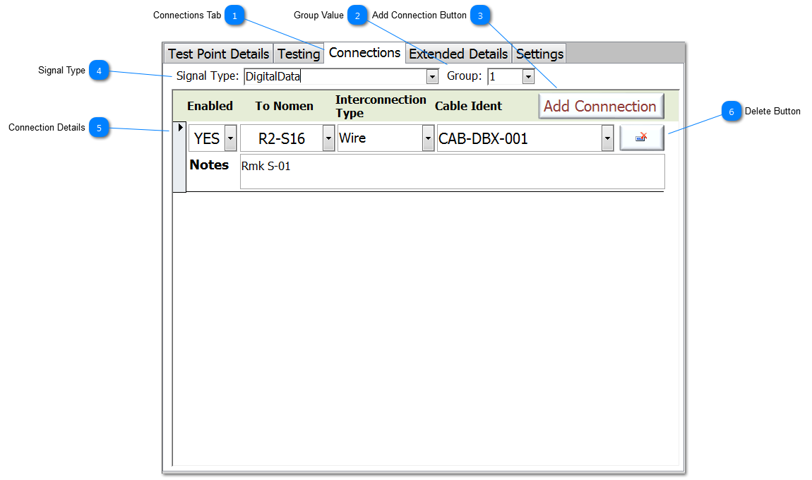
Connections Tab Each TP can have multiple Connections (also known as an entry in a FromTo list). Connections can be added/editted via the Connections Tab on the Test Point Add/Edit form.
A Connections is deemed as a physical connection from the current TP to another TP on the same node. This connection would have a interconnection type, and may have a cable identification.
|
 Group Value Assigning a Group to a TP is different to assigning a Node. Where a Node is an assignment of TPs on the same electrical circuit, Group can be used for other assignments such as physical position, connector, system. This means a TP can be assigned a Group value and thus by this assignment be associated with other TPs that may, or may not, be electrically connected. This can be very useful during fault diagnosis when a whole connector may need to be isolated from the test.
|
 Add Connection Button To add a new Connection for this TP, click on the Add Connection button.
|
 Signal Type
s can be assigned to each TP to allow an better understanding of the circuit during deep diagnosis of a fault. It could be argued that every TP on a specified node should have the same Signal Type ie 'Vertical Gyro + Data'. However, while this is generally true, in some schematics, TPs carrying the same signal type on a common nodal connection might be referenced differently. For example for the same signal:
-
TP1 (Node1) might be 'Vertical Gyro + Data a' -
TP34 (Node1) might be 'Vertical Gyro + Data b' -
TP78 (Node1G) might be 'Vertical Gyro + Data rtn' So these subtle difference describe a deeper level of the signal type.
Enter a Signal Types, existing entries will appear in the dropdown. Remaining disciplined during data entry will help find and sort TPs, and thus help with fault diagnosis.
|
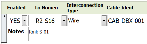
 Connection Details Each Connection entry can be enabled or disabled, and it has associated information relevant to the connection; this includes the Nomen of the connection's end point, the interconnection type and the cable identification, plus the ability to add notes.
Note that Nodal Ground are by definition, the end point, and so they will not have any connections, or their connection will be disabled.
For non-Nodal Grounds, if no Connections have been assigned before the UUT has been validated for testing, then appropriate connections will be add by NODES™.
|
 Delete Button To Delete a Connection, click on the delete button (shown as a record delete symbol) adjacent to the relevant Connection.
|
Made with help of Dr.Explain
|