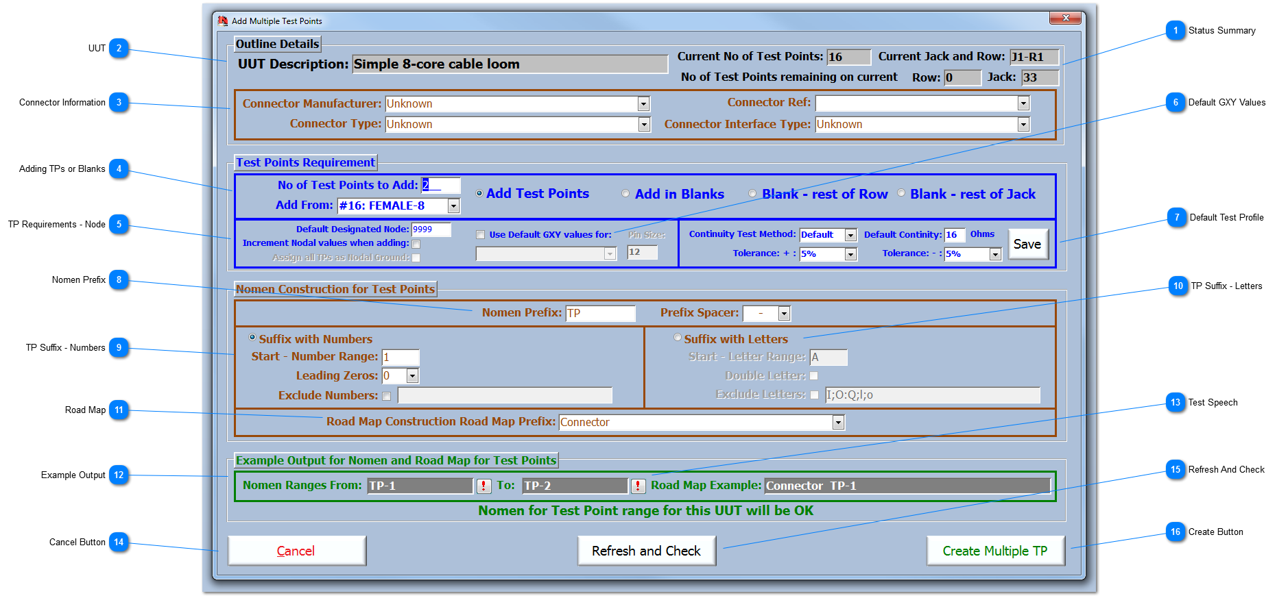
Status Summary This status summary tells the User how many TPs are already assigned for the current UUT and the identification of the Jack and Row that the last TP in the series is on. This status summary also highlights the number of TPs remaining on the current Row and Jack. This information is useful if, for example, there are only 1 or 2 TPs on a Jack, and the User is planning to put the next 25-way connector on one Jack rather than split the 25-way connector over two Jacks, which hampers the build of the ITA.
If the Virginia Panel format is being used as the main ITA interface, then clearly the Rows and Jacks references are not relevant. However, the IFD™ hardware is structured in terms of 3 rows of 8 TP per Jack, and therefore in adding TPs it is worth seeing the TPs in relation to the IFD™ hardware; plus it makes it easier to apply some of the rules that exist for building ITAs with reference to Rows & Jacks.
|
 UUT UUT Description
|
 Connector Information Add Multiple TP is best used for adding multiple TPs for a particular connector or for a discrete part of an interface to a UUT. Therefore, if the User knows the details of the connector, then these can be entered here and they will be applied to every TP add during the multiple TP session.
|
 Adding TPs or Blanks Enter the number of TP required (maximum is 256 for number suffix and 26 for letter suffix). TPs can be either added to the end of the existing TP structure or they can be inserted at a User defined point; be aware, that the latter of these options will change the pin assignments on the IFD™ TE.
There are times when the design of the ITA requires only a few of the TPs to be used on a Row or even a Jack. Therefore, to ensure optimum testing during Intermittence testing, it is important to skip (BLANK) the TPs not being used on a Row. Also there may be a need to keep certain connections to the UUT on separate Jack connectors, for ease of build for example, or for set-up and/or testing; hence the need to skip TPs on a Row or Jack.
|
 TP Requirements - Node A designated node can be entered here. Clearly the Nodal value is unlikely to be the same for all TP that are being added; however, if a number like 9999 is applied, then it will be easy to see them in the TP summary on the Test Point Add/Edit form. Once added, the new TP can then be dynamically filtered using the 9999 value and provide the User with a quick method of editing them accordingly. An option to increment the Nodal value by 1 for each test point is available. Plus an option to assign each of the newly added test points as Nodal Grounds; this option is only available when combined with the incrementing of Nodal values.
|
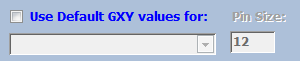
 Default GXY Values The option to apply the default X, Y coordinates and the size of the pin marker automatically during TP creation can be set here.
|
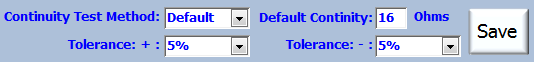
 Default Test Profile Add the generic values for the Default Test Profile - CON-Default. These can be changed by the User by individual TP if required. Use the Save button to save the values as the default
|
 Nomen Prefix The User can use these two fields to define the prefix of the TP nomenclature (no spaces are allowed). Remember that the TP nomenclature is only 10 characters long and so some careful planning on the TP naming convention is required.
|
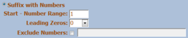
 TP Suffix - Numbers Check the radio button to select the option to apply a Number Suffix to the series of TPs. Use these fields to define the TP suffix, to provide a range of numbers for each of the TPs, to enter a start number (the last TP + 1), and to set how many leading zeros. Once the fields are updated, the results are shown in the Example Output at the bottom of the form.
|
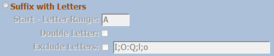
 TP Suffix - Letters Check the radio button to select the option to apply a Letter Suffix to the series of TPs. Use these fields to define the TP suffix, to provide a range of letters for each of the TPs, enter a start letter either lower or upper case. Options to apply double letters and exclude letters are then made available. Once the fields are updated, the results are shown in the Example Output at the bottom of the form.
|
 Road Map Enter the Road Map prefix to construct a unique Road Map for this specific session. The dropdown is self-populating and contains unique entries from the current UUT to remind the User of previous used syntax.
|
 Example Output The Example Output fields are updated whenever any of the fields that affect the TP nomenclature are changed. While the Start and To Example are shown, all output TP nomenclatures are checked against existing TPs for the current UUT to ensure no duplicates are created. A message informs the User whether the selection is OK or if the selections will create duplicate nomenclatures for the UUT.
|
 Test Speech During IFD™ testing, there are options to provide a voice output that identifies the TP by its nomenclature. To test what this will sound like before committing to a prefix and suffix sequence, click on this button to hear the nomenclature (this requires Microsoft Speech SDK 5.1 (min) to be installed on the system).
|
 Cancel Button Click to cancel this operation.
|
 Refresh And Check Use this function to refresh all the fields and check for uniqueness in the names and numbering of the sequence of Test Points being created.
|
 Create Button Click to Create the Multiple TPs and return back to the Test Point Add/Edit form.
|
Made with help of Dr.Explain
|