Due to the vast array of possible connectors and connection types that may be encountered on the UUT, a specific interface has to be designed and made for each testing problem that arises. Once commissioned, this Interface Test Adapter (ITA) can then be used to perform all the IFD™ tests.
Copernicus Technology Ltd has provided the User with the NODES™ software package to enable the User to quickly input/import the electrical circuit information for each of the test points to be tested on the UUT. Once basic UUT details and the test points have been entered into NODES™, a pin-out for manufacture of the ITA can be printed and the relevant testing files for the IFD™ TE can be created. More information about ITA can be found in ‘How to Design an Interface Adapter’ and ‘How to Build an Interface Adapter’.
Using the interface information created using NODES™, the ITA can now be manufactured.
For the IDFIS™, the ITA is normally manufactured based on the 1280-pin Virginia Panel connectors.
For the VIFD™, the ITA is normally manufactured from 50-pin D-sub pre-manufactured cables which are then extended out to connectors which directly connect to the UUT.
See Connector Types for more information on these formats.
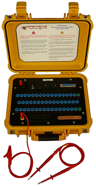
For the VIFD™, the build, test and verification of the ITA can be facilitated by the use of the Copernicus Technology Ltd’s Break-out-Box (BoB MkII), pictured below.
BoB MkII is specifically designed to provide instant identification of cables within the 50-pin D-sub connector when constructing an ITA. It can also be used to carry out additional testing facilities using 3rd party equipment connected to the UUT via the BoB and the IFD™-compatible ITA. For more details on the use of the Break-out-box goto BoB MkII or open the dedicated help file on this device.