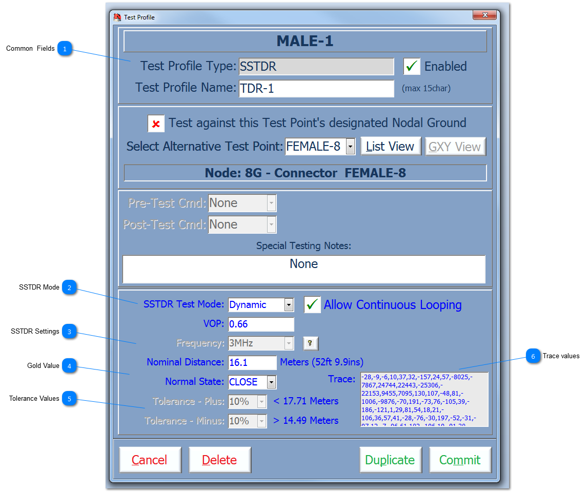
Common Fields |
 SSTDR Mode The SSTDR has 2 modes available, Static and Dynamic. Static is a complex test that spans a number of key frequencies to create an accurate distance to fault calculation; this test can take up to 1sec for each run of the test. Dynamic is a faster and defined test that provides distance to fault on a specified frequency and it will count the number of changed states in a given test.
Allow Continuous Looping allow the test to loop until halted; this mode can only be performed if the SSTDR application is visible.
|
 SSTDR Settings SSTDR setting detailed are specific to the UUT and the TPs being tested.
The VOP (Velocity of Propagation) is a decimal percentage of the speed of electrons in cable compared to the speed of light. Different cable types have different VOP values; even a similar cable type but laid out straight vs a coiled cable will have a slightly different VOP. The VOP needs to set for a give cable type and configuration.
The frequency is defaulted to 3Mhz which is a mid-range frequency for the SSTDR for most applications. If the UUT's TPs are longer, then use a lower frequency, if shorter, then a higher frequency. This parameter is locked because swapping frequencies can takes up to 3secs; User need to be aware that if a sequence of tests are scheduled where the frequency keeps changing between Test Profiles, then a full test could take quite a long-time. Use the Unlock button to allow the changing of the frequency setting.
|
 Gold Value The Gold value is defined in meters and is directly related to the VOP; if the VOP changes, then the Gold value will change. The Gold value can be set as either a theoretical value for this test or can be set as part of the SSTDR Testing. If a true Gold has already been set, shown by Trace values (as shown), then any changes to the Gold values, will null and void the Trace values and this will be set to 'None'. The Normal State is provided to allow the User to define if the cable is normally Open or Close circuit.
|
 Tolerance Values These fields are used to set the tolerances that will be used during the SSTDR test using this profile.
Both Tolerance fields can be expressed in a number of different formats, ie as a absolute value in meters or as percentage of the Gold value. If the value is in the 'Plus' field, then this tolerance is added to the Gold value; conversely if the value is in the 'Minus' field then this tolerance is subtracted from the Gold value. These upper and lower tolerances are then compared to the measured value. Examples formats are as follows:
-
5% Þ 5% is either added or subtracted to the Gold value for comparison. -
1.5 Þ 1.5meters is either added or subtracted to the Gold value for comparison. The Upper and Lower tolerances are calculated on leaving the respective field to allow the User to see the tolerance band applied in meters.
Currently, these fields are fixed at 10%.
|
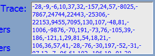
 Trace values This field shows the Trace values captured and plotted by the SSTDR. These values can be selected and then copied to the clipboard; then plotted using an external application.
This field cannot be edited.
|
Made with help of Dr.Explain
|