IFD-Alpha Method
Using the IFD-Alpha method provides the User with full access to the entire testing functionality and fully flexibility in carrying out ad-hoc testing. Within this mode, the nodes become discrete and each node requires a nodal ground. The maximum number of test lines that is needed to be connected in this mode is shown below as 11; for IFD-Beta Method, the same UUT only needs 8.
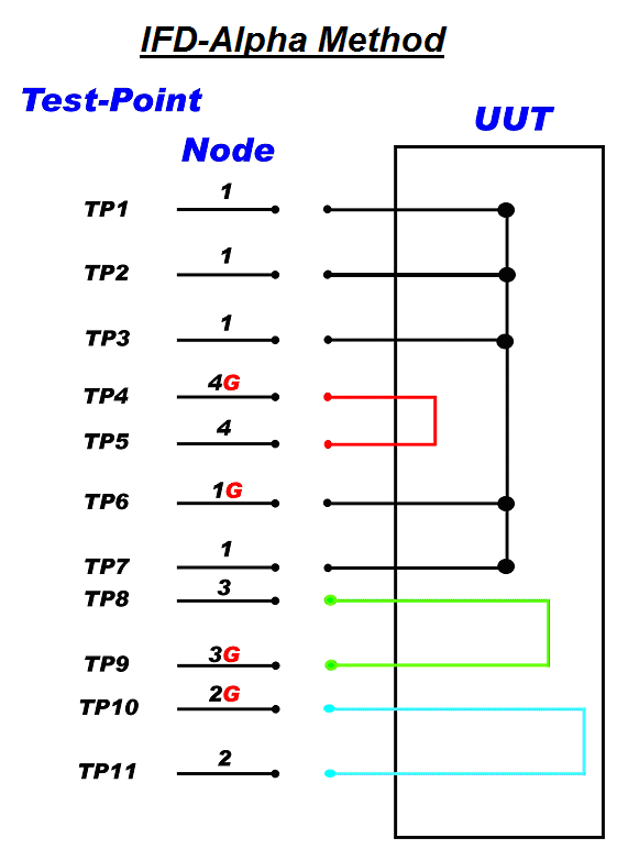
Each test line connected to the UUT should be checked against the other lines to ascertain if it is connected to any other line; each set of ‘common’ test lines should be allocated to a node and each node should have one of the lines assigned as the nodal ground ie the common return line or also known as a 'test ground'. This return line is annotated with a ‘G’ following the node number, but it is still connected to a discrete test point (for VIFD™ NOT pins 17/50 on connectors J1 to J5 or pins 17-50 on connector J6).
In the diagram above, TP1, TP2, TP3, TP6 & TP7 are all interconnected within the UUT. Therefore, they are all allocated and identified as Node 1 and one of the interconnected lines, in this case TP6, has been allocated to the duty of ‘test ground’ and given the node identity of 1G.
TP10 & TP11 are both interconnected and allocated Node 2 identification, and TP10 has been given the ‘test ground’ duty and an allocation of 2G.
TP8 & TP9 and TP5 & TP4 are wired similarly and so are allocated Node 3 & 3G and Node 4 & 4G respectively.