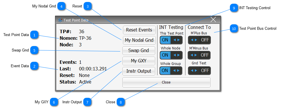
 Test Point Data The core test point data for the associated TP for this popup.
Node will display with the following nomenclature structure:
-
TP on the node value shown - no suffix -
If the TP is a Nodal Ground - suffix G -
TP changed by the user as a Nodal Ground - suffix G-Cx -
TP changed from a Nodal Ground by the User to another TP - suffix G-Des
|
 Event Data The current event data for the TP shown in the popup.
-
Events: will also show if there have been events captured beyond the Glitch Limit (normal as a result of a complex intermittence ie a short).
-
Last: shows the last time an event was captured for this TP.
-
Reset: show the last time the TP was reset, and then how many times it has been reset ie 00:00:24 (2x)
-
-
Active - means the test point is being tested for intermittence in the Neural Network -
Grounded - means that a TP has been connected to Test Ground, and is no longer Active. -
Suspended - means that the TP has been removed from the Neural Network, and is no longer Active, or connected to any measurement bus. -
Combined - means the TP may be connected to one/or more measurement buses, and/or the Neural Network.
|
 Reset Reset the test point back to the original condition defined at the start of the test.
An Event-Log action will be registered in the Log File for reference and the Reset: will show the test time the reset occurred.
|
 My Nodal Gnd Click to open a similar popup for the associated Nodal Ground for the test point currently being shown.
|
 Swap Gnd Click to open the a table with the Node associated TPs. The table presented will allow the User to select another TP as the Nodal Ground. See Test Point Ground Swap for more details. |
 My GXY Click to show the GXY Viewer for the UUT. The displayed GXY Viewer will be pre-filtered for the associated Node. |
 Instr Output |
 Close Close the popup. Note that these popup will disappear after a set period of time if they have not been interacted with.
|
 INT Testing Control This Test Point - allows the User to remove/suspend (OFF), or activate (ON) the designated TP for intermittent testing.
Whole Node - allows the User to remove/suspend (OFF), or activate (ON) all TPs associated with the shown TP's Node for intermittent testing.
Whole Group - allows the User to remove/suspend (OFF), or activate (ON) all TPs associated with the shown TP's Group for intermittent testing.
|
 Test Point Bus Control Toggle buttons that allow the User to assign the TP to different measurement buses as required.
Note that a TP can't be assigned to the M'Plus and M'Minus at the same time.
|
Made with help of Dr.Explain
|


