Keysight
Installation for IFD™ TE Rack-Mount variants
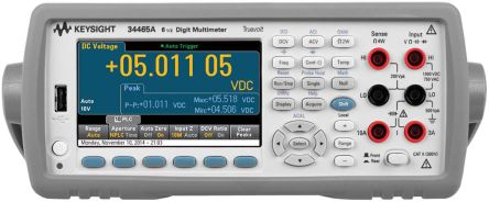
Ø Supported Devices Keysight: 3446x
Post 2016, it is likely that the Keysight 3446x is installed as the DMM of choice to provide DMM support.
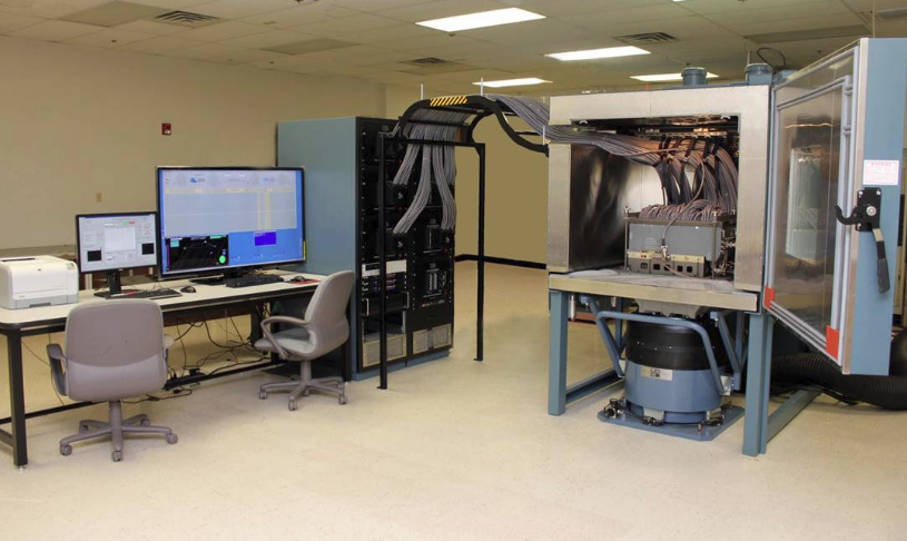
Connecting Device
Use the connection shown below for the Keysight device:
All IFD™ continuity based tests need the 34465a to be connected using pass-through Ethernet cable to connect to the LAN of the CC.
NODES™ can carry out basic point2point continuity tests and supported Keysight devices can be connected using a number of methods by either using Ethernet peer to peer on a LAN as resource or by USB; note to use the appropriate connection string for LAN and USB in the DMM Options.
Connection to the IFD™ TE is via the high-quality LEMO provided on the rack-mounted equipment, to the front or the rear panel of the Agilent.
Basic Settings
Ø The Keysight's settings can be carried out using the keys on the front panel.
Pressing the front panel keys; Shift-Utility
Select the following (refer to Agilent’s operating instructions if necessary):
-
Remote I/O
-
Enable LAN (Yes)
-
LAN Settings (manual)
-
IP Address: 169.254.4.61
-
Subnet Mask: 255.255.0.0
-
Default Gate: 0.0.0.0
-
DNS Server: 0.0.0.0
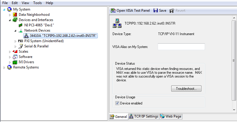
Ø If installed, open NI-MAX and navigate to the Network Devices and select 34410A, from here select the Web Page option at the bottom of the page to show the settings of the Agilent.
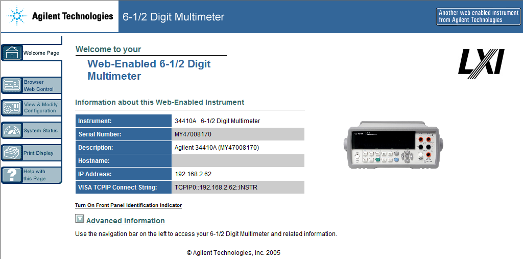
Select 'View & Modify Configuration' and set the basic settings:
-
Remote I/O
-
Enable LAN (Yes)
-
LAN Settings (manual)
-
IP Address: 169.254.4.61
-
Subnet Mask: 255.255.0.0
-
Default Gate: 0.0.0.0
-
DNS Server: 0.0.0.0
Or use the Factory Defaults button to reset to these settings.
Factory default connection string for a Agilent 34410a is "eg TCPIPO::169.254.4.61::inst0::INSTR"

To avoid possible damage to the IFD™ TE
or the equipment under test, follow these guidelines:
· Do not use this equipment on any “powered” circuits. The IFD™ TE supplies the entire electronic testing stimulus needed. Failure to do so could damage the equipment and void the factory warranty.
· Do not connect the IFD™ TE system to any additional test equipment that produces stimulated High Voltages or Currents that might damage the IFD™ hardware, and this will include insulation tests and it may include some Diode testing; if unsure then contact your Distributor for more information before proceeding.