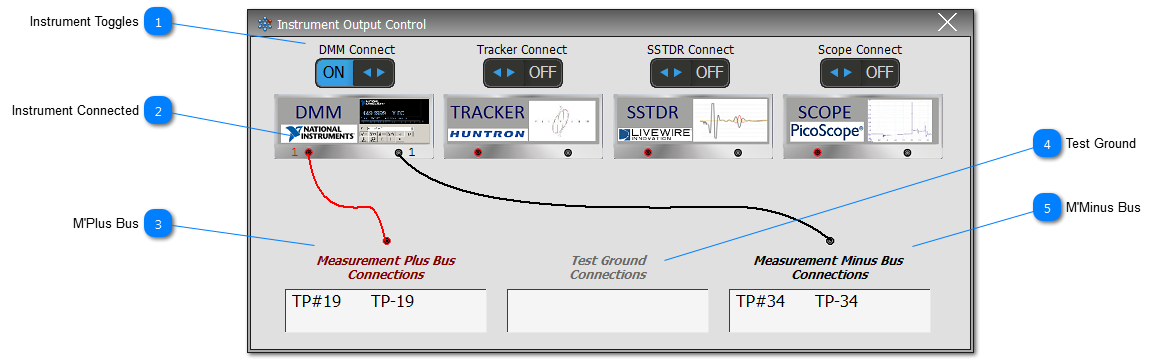
Each Instrument fitted can have its inputs connected to the Measurement Bus: Measurement Plus Bus (M'Plus or M+) and/or Measurement Minus Bus (M'Minus or M-).
Users must note that by connecting more than one instrument on to the Measurement Buses at any one time (which is possible) could have an adverse affect on the reading/s provided by the varies instrumentation that have been connected; this is because the instrumentation is generally not isolated when taking its readings. Also if a TP is still left on the IFD bus, which is part of the Neural Network during Intermittence Testing, then a voltage may well be sensed on the Measurement Bus.
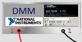
Each instrument will show whether it is connected to the Measurement Buses by means of the interconnecting line shown here for the DMM. The number (shown as 1 for this example) indicates which module has been connected. If more than one module, in a multiple module system, is connected, then it will show 'C' for combination. If all modules are connected to the same bus, then it will show 'A'.
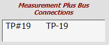
The list shows the TPs connected to the M'Plus Bus. The Test Point Data Display can be revealed for any given test point listed by double-clicking on the test point nomenclature.
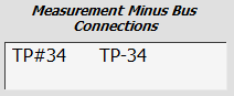
The list shows the TPs connected to the M'Minus Bus. The Test Point Data Display can be revealed for any given test point listed by double-clicking on the test point nomenclature.