To reduce the risk of fire or electric shock or equipment damage,
do not use the IFD™ TE or BoB MkII on any powered circuit.
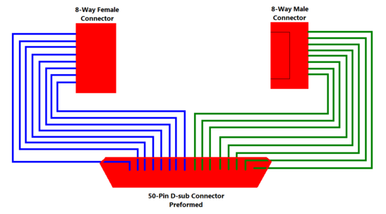
As an example for the VIFD™, the UUT being used as the Test Piece is a simple 8-core loom with a female connector at one end and male connector at the other. The design of the ITA has been covered under Designing an ITA and Creating the ITA Pin-Outs, and for this example the UUT has been designed using IFD-Alpha method, with all pins connected to the IFD™ TE.
Therefore, the ITA needs to be a 50-pin D-sub connector connected to an 8-way male and an 8-way female connector. A preformed 50-pin D-sub connector was selected as the main interface to the VIFD™, and the 8-way connectors were matched to the UUT. The schematic of the ITA is below.
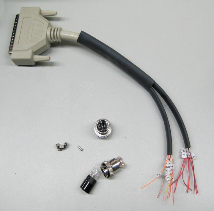
Using the schematic and the Basic Pin-Out report from NODES™, the 16-cores needed for the ITA were identified and labelled, and the remaining cables tied back (it is suggested that spare cables are kept just in case additional TPs need to be addedto the ITA in the future or cables within the ITA need to be replaced due to wear and tear).
Preparation of ITA
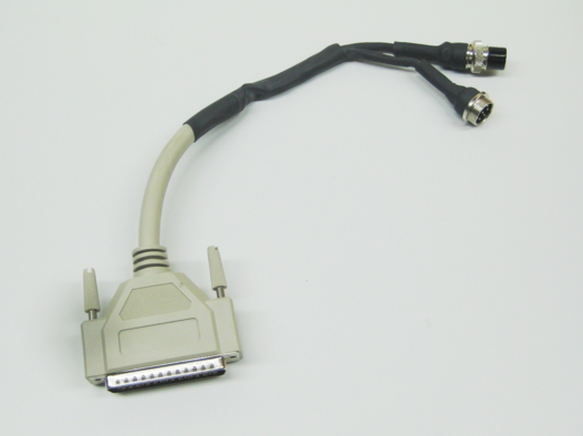
Completed ITA
With cables identified on the 50-way using the BoB MkII to help identify each of the 16 cables on the 50-way cable, the ITA build was then completed. The use of heatshrink and cable restraints should be considered by the User during the design process, and it is strongly suggested that the light gauged cables on the 50-way are protected to maintain the integrity of the ITA at all times.
Once the interface cable is complete, it is strongly recommended that it should be fully tested by using the BoB MkII to confirm correct identification and continuity. It is also recommended that interface assemblies that may be required to test many UUTs over a long period of time be constructed to the highest standards possible, and be subject to testing periodically.
For accurate fault finding and intermittent fault analysis it is crucial that all test connections created in the ITA between the IFD™ TE and the UUT should be soldered or should employ precision termination methods, such as crimping, wherever possible. This will help to reduce any spurious indications, high resistances or faults from outside influences entering into the results for the UUT.
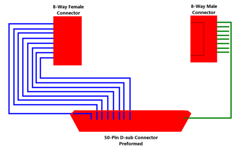
If the IFD™ TE was testing the loom in the more simplified configuration using perhaps IFD-Beta method, then the schematic wiring would be as shown below. This difference would also have to be reflected while entering the test points into NODES™ for the Test Loom resulting in a requirement for only 8 test points in total with a common return to either pin 17/50 on the 50-Pin D-Sub connector for Model0 & Model1 and for other Models an assigned test point that will be assigned as a nodel ground within NODES™; for this example this is shown as TP16 in the topic IFD-Beta Method. For Model6 IFD™ TE and above, Pin 17/50 are not designated test grounds and so for these models, a dedicated test point has to be assigned.