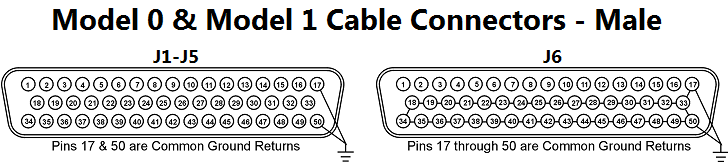
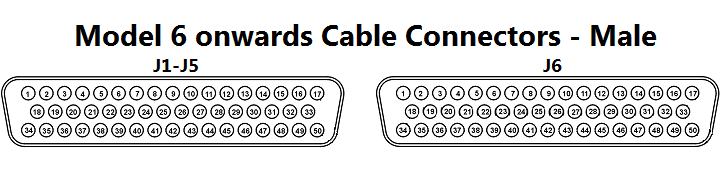
Depending on the Model of the IFD™ TE depends on how Pin17 & Pin50 are connected on J1-J6 and the second row are connected on J6 within the IFD™ TE.
For IFD™ TE with 512 test points, J7-J12 are a direct copy of J1-J6.
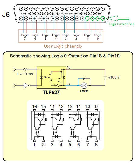
First Row of J6
To allow 48-way and 50-Way ITA to be used on Model 6 onwards IFD™ TE
Pin17 & Pin50 are connected in parallel to the following connections on J6
J1-Pin17 is routed from J6-Pin7 (Test Point 247)
J1-Pin50 is routed from J6-Pin8 (Test Point 248)
J2-Pin17 is routed from J6-Pin9 (Test Point 249)
J2-Pin50 is routed from J6-Pin10 (Test Point 250)
J3-Pin17 is routed from J6-Pin11 (Test Point 251)
J3-Pin50 is routed from J6-Pin12 (Test Point 252)
J4-Pin17 is routed from J6-Pin13 (Test Point 253)
J4-Pin50 is routed from J6-Pin14 (Test Point 254)
J5-Pin17 is routed from J6-Pin15 (Test Point 255)
J5-Pin50 is routed from J6-Pin16 (Test Point 256)
User Logic
Second Row of J6
J6-Pin18 to J6-Pin33 are outputs for digital switching for Smart Interface Adaptors.
Digital Channel 0 - Collector on J6-18 & Emitter on J6-Pin19
Digital Channel 1 - Collector on J6-20 & Emitter on J6-Pin21
Digital Channel 2 - Collector on J6-39 & Emitter on J6-Pin23
Digital Channel 3 - Collector on J6-41 & Emitter on J6-Pin25
Digital Channel 4 - Collector on J6-43 & Emitter on J6-Pin27
Digital Channel 5 - Collector on J6-45 & Emitter on J6-Pin29
Digital Channel 6 - Collector on J6-47 & Emitter on J6-Pin31
Digital Channel 7 - Collector on J6-49 & Emitter on J6-Pin33
Third Row of J6
High Current Test Ground
J6-34, 35, 36, 37 (used for high count nodes greater than 80)
From the ITA pin-out and the cable selected, the User will need to identify each of the cables in association with its corresponding pin and then connect this to the UUT interface connector. This process is made easier with a specially designed break-out-box called the
BoB MkII which can be sourced from Copernicus Technology Ltd. BoB MkII has been specifically designed to simplify and speed up the manufacture of interface cable assemblies. It does this by enabling the rapid identification of each of the cables during the build of the ITA, and can then be used to test the ITA. When connected to the UUT, the BoB MkII can also be used to connect the UUT to other test equipment types. This means that the ITA allows connectivity with the fullest possible range of relevant testers.
The construction of an ITA is relatively straightforward process, however, if additional training or advice is required in their design or manufacture then contact Copernicus Technology Ltd. Continuing the theme of the Test Piece described in Designing an ITA, go to
ITA Build for Test Piece.