Tests
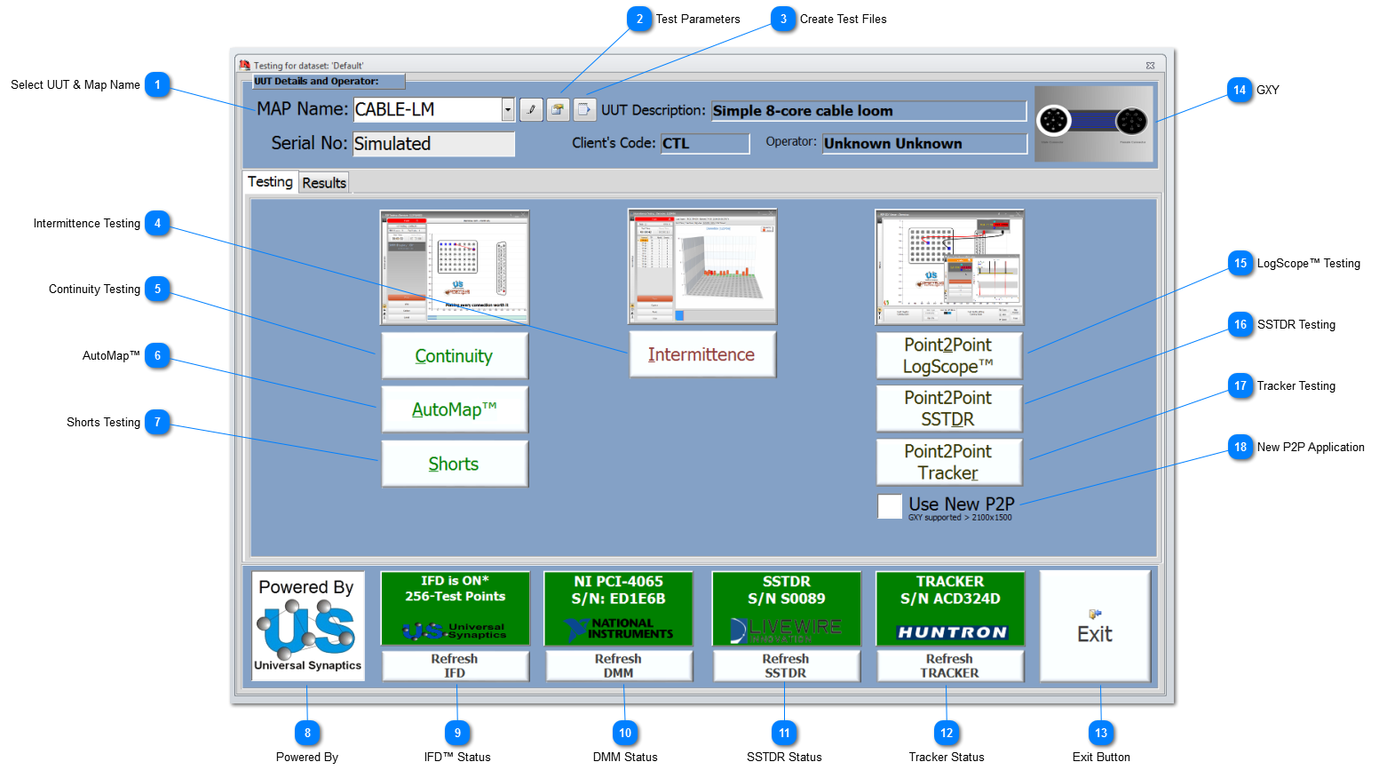

Test Parameters Select to change the settings and parameters for all the testing methods. These Testing Parameters will be used throughout the various tests carried and are recorded in the associated reports. If Test Parameters have not been set, then on selecting a test, the User will asked if they wish to automatically set the Test Parameters to the defaults or open the Testing Parameters form so they can be individually set.
|
Create Test Files Use this function to create stand-alone Test Files independent from NODES™; see File Creation for more details.
|
Intermittence Testing  Select to carry out Intermittent Fault Detection and Isolation using the Intermittence Testing application for the selected UUT. The traditional Legacy Intermittence application is only available on request.
|
Continuity Testing  Select to perform a Continuity Test on the selected UUT, using CON-Default Test Profile and other continuity Test Profiles as selected.
|
AutoMap™  Select to perform an AutoMap™ of a UUT.
|
Shorts Testing  Select to perform a Shorts Test on the selected UUT.
If shorts are found during the Shorts Test, the Trace button will appear in the P2P Testing application. Select to perform a Trace Test on the selected UUT.
|
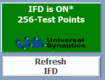
Powered By  The world-leading IFD™ Technology and its associated hardware & processes are powered by Universal Synaptics Corporation.
|
DMM Status 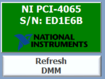 Shows the status of the DMM selected by NODES™ to perform automatic and User selected Click&Test™ testing. The DMM status indication shows Green if there is a valid DMM fitted and connected with a valid serial number indicated. The panel will show in Orange if the DMM is in simulated mode. To Refresh the DMM, click on the Refresh DMM button. To setup the DMM, and its connecting string, double-click on the DMM Status panel. To setup a new DMM or review a DMM's setting, including finding the device's connections string etc, refer to the NI-Max topic.
|
SSTDR Status  The SSTDR Status panel will show in Green if fitted and connected with a valid serial number displayed. The SSTDR's serial number has to be entered into SPIDER™ in the appropriate field. If there is no serial number entered or 'None', then the SSTDR will not try and connect, and the SSTDR functions will not be made available. To run SSTDR functions in simulated mode (status is shown in Orange), then enter a serial number in SPIDER™ that starts with the phase 'Sim'. To Refresh the SSTDR, click on the Refresh SSTDR button.
|
Tracker Status  The Tracker Status panel will show in Green if fitted and connected with a valid serial number displayed. The Tracker's serial number has to be entered into SPIDER™ in the appropriate field. If there is no serial number entered or 'None', then the Tracker will not try and connect, and the Tracker functions will not be made available. To run Tracker functions in simulated mode (status is shown in Orange), then enter a serial number in SPIDER™ that start with the phase 'Sim'. To Refresh the Tracker, click on the Refresh TRACKER button.
|

LogScope™ Testing  Select this option to open the Point2Point application and display the GXY graphic ready for test point selection.
The test mode will default to Continuity. Using the GXY, mouse-over the various TPs and select two TP to perform a Click&Test™ for LogScope™. Other test modes will be made available from the GXY including Diode Testing, and depending on model and options, and may include: SSTDR Testing, Tracker Testing and the ability to connect to an External Instrumentation connector.
|
SSTDR Testing  Select this option to open the Point2Point application and display the GXY graphic ready for test point selection.
The test mode will default to SSTDR. Using the GXY, mouse-over the various TPs and select two TP to perform a Click&Test™ for SSTDR. Other test modes will be made available from the GXY including LogScope™ Testing, Diode Testing, and depending on model and options, and may include: Tracker Testing and the ability to connect to an External Instrumentation connector.
If a SSTDR is not fitted, or simulated, this option will not be made available.
|
Tracker Testing  Select this option to open the Point2Point application and display the GXY graphic ready for test point selection.
The test mode will default to Tracker. Using the GXY, mouse-over the various TPs and select two TP to perform a Click&Test™ for Tracker. Other test modes will be made available from the GXY including LogScope™ Testing, Diode Testing, and depending on model and options, and may include: SSTDR Testing and the ability to connect to an External Instrumentation connector.
If a Tracker is not fitted, or simulated, this option will not be made available.
|