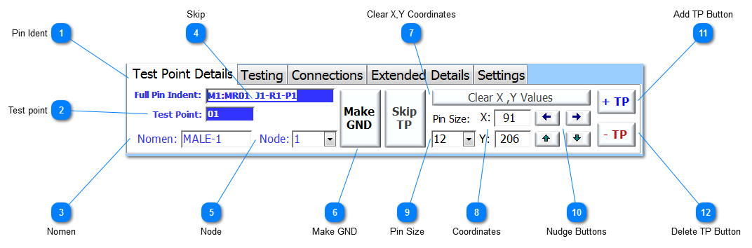
Pin Ident For a 48-Way format connector, the full identity of the Pin for this TP (as shown) is:
|
 Test point Test Point number as referenced by the testing applications and used to configure the IFD™ hardware.
|
 Nomen Nomenclature of the Test Point. This has to be unique for the UUT and it can be up to 10 characters long, with no spaces allowed. It is preferred if the Nomen does not start with a number.
|
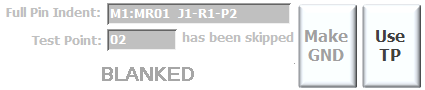
 Skip Click to skip the current TP. It may be that the designer of the ITA, might want to have certain J-connectors for certain connections to a specific part of the UUT. In this case, there may be TPs on a J-connector or Row, that might not be connected and therefore it will need to be skipped. Skipping a TP disables the associated details for this TP but allows the User to define a marker position which is displayed in Grey. The button then toggles to show Use TP.
|
 Node Each TP should be attributed to a Node; see more on Nodes in Designing an ITA. A dropdown of numbers is available from 1-30; the User is able to enter integers beyond 30 as required. There is an option of using a designated nodal number of 9999, and allows the User to apply a Nodal value if a true nodal path is unknown. This 'Dummy Nodal Number' then allows an easy search using the Dynamic search facility to find unassigned Nodal values across the Test Point data. If the dummy value is applied, then by double-clicking in the field automatically assigns then next Nodal value.
This Dummy Nodal Number can be used in AutoMap™ to limit the AutoMap function to just 9999. This is a useful tool for tracing specific TPs or complete Nodes assigned with the Dummy Nodal Number of 9999. See AutoMap™ Test for more details. |
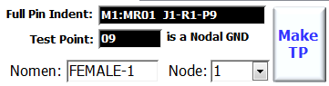
 Make GND Each Node has to be assigned a Nodal Ground. Click the Make GND button to toggle the Test Point as a Nodal Ground, as shown this Test Point is not a Nodal Ground as it is coloured blue. If the Test Point is been assigned as a Nodal Ground then the colouring will be black and the button changes to Make TP.
If a Nodal Ground has already been assigned, NODES™ will inform the User which TP has already been assigned as the Nodal Ground.
If the UUT has been designated IFD Mode, then this field will be disabled.
|
 Clear X,Y Coordinates Clear X,Y Values allows the User to quick clear the X,Y values and then if required select a new X,Y on the GXY graphic or click on the revealed button
This function is used to set the X,Y coordinates for the current TP to the default X,Y coordinates. This is only useful when the UUT does not have a specific GXY graphic and has been assigned the Default GXY graphic. If there are coordinates assigned this button will toggle back to Clear X,Y Coordinates.
|
 Coordinates X,Y coordinates can be assigned to each TP. These coordinates relate to the pixel on the GXY graphic with (0,0) being the top-left of the graphic. Coordinates can be entered manually in the fields shown, or they can be entered directly on to the GXY graphic on the Test Point Add/Edit form. If the coordinate fields are empty, then the cross-hair cursor  will appear if the mouse is moved over the GXY graphic. Click on the GXY graphic to assign the relative coordinates to the current TP. If the coordinates are already populated, then press the Ctl key to display the cross-hair cursor. |
 Pin Size Enter the pin size of the TP as it will be displayed on the GXY graphic. The pin size is the width of the TP marker on the GXY graphic.
This field does not relate to the actual pin dimension, and is only used for graphical representation.
|
 Nudge Buttons Use the four Nudge buttons to move the TP on the GXY graphic by 1 pixel for each press in the direction shown on the Nudge button.
|
 Add TP Button Add a single TP to the UUT. Each press creates a new TP with the system and User defined defaults, and the focus is set to the Nomen. This can be time consuming for complex IAs and so a facility called Add Multiple TP is available. |
 Delete TP Button Click to delete a TP. TPs can only be deleted completely from a UUT if they are the last in the series of TPs. If a selected TP needs to be deleted but it exists before the last TP in the series, then it will be marked as Skipped and the Nomen set to BLANK.
|
Made with help of Dr.Explain
|