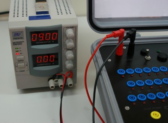
Pre-use checks of BoB MKII can be carried out in either the ‘Bench’ or ‘Field’ modes of operation. In the ‘Bench’ mode, the BoB MKII requires connecting to a 9VDC supply from a stabilised power supply, see figure below; in ‘Field’ mode the BoB MKII utilises an internal battery 9VDC supply.
1. All test leads, BoB MKII surface mounted components, fixtures and fittings should be visually examined for damage, deterioration and security prior to use and any problems should be corrected or the BoB MKII returned for maintenance.
2. If in ‘Field’ mode, check for the presence of a serviceable internal battery and fit or replace as required with a 9VDC PP3 cell only. Do not attempt to use any other battery configuration or type.
3. BoB MKII can still be used in the ‘Bench’ mode of operation with no internal battery fitted.
4. Select the power switch to the ‘BAT.’ Position and momentarily depress the test button. The LED should illuminate a bright green and an audible high pitch buzzer should be clearly heard.
5. Any failure of the LED to illuminate brightly or buzzer to sound should be regarded as a self-test failure and battery replacement action should be carried out.
6. If the BoB MKII is to be used in the ‘Field’ mode, the power switch should be left in the ‘BAT’ position, now continue from step 13.
7. If the BoB MKII is to be used in the ‘Bench’ mode, the power switch should now be selected to the ‘OFF’ position.
8. The 9VDC bench supply can now be attached to connector points +ve and –ve.
9. The bench supply should be switched on and the power switch selected to ‘EXT’
10. The test button should now be momentarily depressed - the LED should illuminate a bright green, accompanied by an audible high pitch buzzer.
11. Any failure at this point should be initially investigated for the serviceability of the bench supply.
12. The power switch can now be left in the ‘EXT’ position.
13. Any persistence of a failure during the functional test should result in the BoB MKII being considered as faulty and returned for maintenance.
14. If a test probe is required, it should now be connected to the appropriate test point.
15. The continuity of the test probe can be confirmed by momentarily touching any of the 50 test point connectors on the BoB MKII facia panel.
16. This should result in the appropriate connection point LED illumination and buzzer sounding.
17. All 50 test points and LEDs can now be quickly tested in turn to confirm complete serviceability of the indication and test circuits.
18. The continuity of the copper test bar can also be tested by connecting it via a test lead to any of the 50 test point connectors.

